 I
had one of these sets, in a light purple case, when I was a child. It was given
to me by my grandfather, and eventually it stopped working and I pulled it to
pieces as kids do.
I
had one of these sets, in a light purple case, when I was a child. It was given
to me by my grandfather, and eventually it stopped working and I pulled it to
pieces as kids do.Introduction
I
had one of these sets, in a light purple case, when I was a child. It was given
to me by my grandfather, and eventually it stopped working and I pulled it to
pieces as kids do.
I was keen to get hold of another one, so I put a request on this website (and in a couple of other places). Pete Roberts contacted me, and offered to send me his set so I could look at it and make an offer. We agreed on an exchange for two of my CD-ROMs.
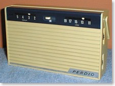
This set is a different colour to the one I had previously, but I have never seen any of these sets at vintage radio swapmeets and fairs, so they may be fairly rare now (probably because many were thrown away when they went wrong years ago).
The set is a small MW/LW model using the infamous AF117 transistors. The four AA size batteries fit in holders on the PCB in a neat square around the speaker magnet. Edge operated volume and tuning controls are on the right side and external aerial/earth and earphone sockets on the left.
 Condition
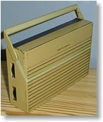
The cabinet was cracked in the top right corner (just visible in this photo), but was otherwise complete. It was originally a pale grey colour but has become discoloured over the years. The areas that were not exposed to light (such as underneath the handle) are still the original colour.
I initially thought this was dirt, but although the set was very dirty, the discolouring seems to be the actual pigment in the plastic (rather like cream panels on photocopiers and fax machines become yellowed over time). The discolouring is very even, which is fortunate.
The tuning drive cord was missing. The pieces were in a plastic bag inside the set, which is fortunate because it would be quite difficult make something the same. The off/waveband slide switch was broken, although it could be provoked into working. The indicator piece that shows through a window below the switch to indicate the waveband was missing.
AF117 Transistor
When I first received the set I put some batteries in it and it worked (with the waveband switch wiggled to make it connect). It could not be tuned due to the missing drive cord, but happened to be tuned to receive a BBC local station. However when I came to repairing it, it had stopped working.
With the back off, I tapped the cases of the AF117 transistors with a screwdriver. Tapping the uppermost AF117 got it working, but only temporarily. AF117 type transistors are notorious for developing internal short circuits between the case connection and one of the other connections.
To dismantle this set, three screws are removed, then the PCB is carefully listed out at al angle to allow the controls to clear their holes in the case. The speaker leads are a reasonable length and don't need to be disconnected. The aerial and earth sockets are connected by short leads, which are soldered to the PCB and clip onto the sockets. These had already dropped off!
The offending AF117 was unsoldered and checked with a meter. It did indeed show short-circuit between collector and case. Andy Emmerson's Electronic Classics book suggests that the short circuit can be blown away by discharging a 50uF capacitor charged to 50V across it. I don't have a 50V PSU so I used the 68V output from my HT02 battery converter and a 47uF 250V capacitor.
I linked the E, B and C leads of the transistor together and discharged the capacitor between this and the case connection. There was a small spark as the leads touched for the first time and the capacitor discharged. Touching the leads for a second time produced no spark, suggesting that it had worked.
Before refitting I checked the transistor using my transistor tester. Alternatively the diode or resistance range of a test meter could be used. It was fine, and when refitted the set worked.
Switch
 The
OFF/MW/LW switch consists of a plastic carrier/lever containing the moving contacts,
operating against tinned track sections on the PCB. The carrier is held in place
with a spring clip at one end, and bumps in the plastic work with the spring
to give the position clicks. The other end has a T-shaped piece that fits in
a slot on the PCB. This piece had broken off, so the switch was not making good
contact. The contact sections on the PCB were also blackened, which didn't help!
There were signs of glue where somebody had attempted to repair the switch previously.
This obviously hadn't worked so as an alternative repair some pieces of plastic
had been cut to fit over the switch lever and bear against the front of the
case. Since this is the back-printed tuning scale I felt this wasn't a good
idea.
The
OFF/MW/LW switch consists of a plastic carrier/lever containing the moving contacts,
operating against tinned track sections on the PCB. The carrier is held in place
with a spring clip at one end, and bumps in the plastic work with the spring
to give the position clicks. The other end has a T-shaped piece that fits in
a slot on the PCB. This piece had broken off, so the switch was not making good
contact. The contact sections on the PCB were also blackened, which didn't help!
There were signs of glue where somebody had attempted to repair the switch previously.
This obviously hadn't worked so as an alternative repair some pieces of plastic
had been cut to fit over the switch lever and bear against the front of the
case. Since this is the back-printed tuning scale I felt this wasn't a good
idea.
Before the switch can be accessed fully the tuning drive back-plate needs to be removed. Normally I would have needed to dismantle the tuning drive to do this, but this was already missing. The plate is thin black aluminium and is held by tabs that pass through slots in the PCB and are twisted on the other side.
With the switch carrier removed I cleaned the PCB contacts and moving contacts with a scouring pad. I fabricated a new T-section using the hollow plastic stick from a cotton-bud and some 24SWG tinned-copper wire. I filed a small locating notch in the end of the carrier, then held the new piece onto the carrier by wrapping the wire around the switch lever and looping the ends together. I then lifted off the formed wire and soldered the looped ends. This photo shows the assembly more clearly than I can describe.
Before finally refitting the switch carrier/lever I cleaned it with foam cleaner.
Capacitor
Next to the switch was one of those little black Hunts capacitors, which was falling to pieces, as they are prone to do. This was the only one of these in the set. I removed it and fitted one of those stripped Mullard C280 PCB types, which is the same type as other capacitors fitted in the set.
Tuning Drive
The original tuning drive cord was complete but was broken. I positioned it back in the set to see what I had. There was insufficient to just tie the broken ends back together. The pointers in this set are small white round plastic beads, pulled along behind the scale by black cord (the idea being that the cord cannot easily be seen against the black background). It was therefore important to retain the black cord where it was visible with the set assembled.
Fortunately the break was in an area that could not been, so I tied a short piece of thin modern white drive cord onto the broken end and completed the run with that. The knots were secured with a drop of Super-glue (I used the version that comes with a brush in the cap) and left for a few minutes to ensure it was dry before applying tension by refitting the spring.
I then tried the board in the case to see how far out the pointer alignment was. I found that the correct positions for the beads so that they cover the full scale is as far out towards their respective ends of the PCB as possible (the beads just touch the pulleys at the end of the travel). With batteries fitted I then checked the calibration. Bearing in mind the basic scale, it was fine on both bands.
Switch Indicator
 I
designed a replacement switch indicator label using CorelDraw 7, printed it
onto glossy photo card using an inkjet printer, cut it out and fitted it. It
took a few attempts to get it right; these were printed on paper to avoid wasting
the expensive card. The idents were as I remember from the set I owned as a
child - "OFF" in narrow letters, and "M" and "L"
as single wider characters. The text is white on a dark blue background so I
needed to use bold characters and the highest resolution setting on the printer
for the best results.
I
designed a replacement switch indicator label using CorelDraw 7, printed it
onto glossy photo card using an inkjet printer, cut it out and fitted it. It
took a few attempts to get it right; these were printed on paper to avoid wasting
the expensive card. The idents were as I remember from the set I owned as a
child - "OFF" in narrow letters, and "M" and "L"
as single wider characters. The text is white on a dark blue background so I
needed to use bold characters and the highest resolution setting on the printer
for the best results.
If you want to download the CorelDRAW file and a higher resolution GIF file of this indicator label (contained in a ZIP file) please click here. File size is 5K.
Battery Connectors
 The
battery contacts were somewhat corroded and tarnished, partly due to previous
leaking batteries. During previous tests I had needed to poke and wiggle the
batteries to get them to make contact, so the contacts clearly needed some attention.
The
battery contacts were somewhat corroded and tarnished, partly due to previous
leaking batteries. During previous tests I had needed to poke and wiggle the
batteries to get them to make contact, so the contacts clearly needed some attention.
The holder is in fact four separate sections fitted to the PCB, each containing a spring negative contact and a solid positive contact, mounted at a right angle to each other.
I desoldered these, and was then able to remove the metal contacts from the plastic supports. Andy Emmerson's book suggests bathroom descaler for removing the effects of leaking batteries, so I put the metal pieces in an aerosol can lid with "Lime Light" descaler for a few minutes. This did get rid of the battery residue but the contacts were still very dull. I then tried some "Instant Brass and Copper Cleaner", which successfully removed some of the tarnishing and left the contacts reasonably presentable. They were not gleaming, but should be clean enough to make a good contact.
The springs on the negative contacts merely pass through a hole in a metal plate and are held between this and the plastic holder. I felt it was possible that this could give rise to connection problems, so soldered the spring to the plate before reassembling.
Wiring
The wires to the speaker were sleeved with that brown woven sleeving that is well known for going sticky. This sticky residue is slightly conductive, so I decided to replace it. I used some modern sleeving of a similar type ("borrowed" from work). The same sleeving was also used on two connections from the ferrite rod, so these were also replaced.
The aerial and earth wires were resoldered to their contact clips and to the PCB. One of these clips was also sleeved with the same sleeving, which I replaced.
Case
The loudspeaker was removed by releasing the two screws, and disconnected. I tried to remove the earphone socket but was unable to release the nut. Rather than risk damaging it, I decided it would have to remain in place while the cabinet was washed.
The handle can be removed by folding it fully forward then carefully pulling the ends out of the holes in the case. The pivots on the handle have tags that align with notches on the holes with the handle in this position. The tuning scale could be removed easily due to the broken top section of the case.
The case, back and handle were then given the usual cleaning treatment with warm water and washing-up liquid. Some of the dirt was fairly stubborn so I left the parts to soak for fifteen minutes before adding some more warm water and carefully scrubbing with a toothbrush. I had run out of old toothbrushes so bought some "Tesco Value" ones at 38p for a pack of two while I was buying the "Lime Light".
During the soaking the metal PERDIO trim started to come away, so I carefully removed it and cleaned it separately. I didn't bother to clean the adhesive side, and once everything was dry I found that the adhesive was sufficiently sticky to allow the trim to be stuck back in place with no new glue being required.
The break had been repaired previously with some brown adhesive (maybe Evo-Stik). Even with all this scraped away the pieces would not fit closely enough to use Super Glue, so I used a plastic cement of the type intended for assembling plastic model kits instead (Revell Contacta Professional, which has a thin metal tube applicator spout). The repair was held together with a couple of elastic bands for several hours while the bond set.
A small part of the dark blue printing on the tuning scale was chipped. This was immediately in front of one of the brass tuning drive pulley shafts on the PCB, so the damage had presumably occurred during attempts to repair the set in the past. I did not have any suitable coloured enamel paint, but did have a lighter blue. I mixed some of this with some black and a bit of mauve to get the right shade. Once the paint was dry I refitted the scale into the cabinet, taking care not to stress the glued joint.
Discolouring
I discussed the discoloured cabinet with various people on the Vintage Wireless email list, and the general agreement was that there was nothing I could do about it. Andy Emmerson summed it up nicely in his message, which was in reply to some suggestions made previously:
I have seen pastel coloured telephones where the blue colour had faded to a pale greyish blue. Aggressive and abrasive grinding, followed by polishing with finer and finer grit, restored the original rich colour. But all surface detail of the moulding was lost and it would be only a matter of time before the colour faded again in the ultra-violet.
If you see that nicotine brown colour, then the plastic has passed point of no return, simply because the added pigment has vanished. The brown is the natural colour of the moulding material. I know just how frustrating this is. So do all the collectors of early home computers. In the past, I've had reasonable success with acrylic spray paint. However, it is less convincing on smooth plastic surfaces.
There's a guy in London who resprays 1960s telephones into 'pop' colours and dyes the curly cords (you can see his efforts at Flying Duck Enterprises opposite Greenwich DLR station and in other 'cult' kitsch shops and markets). I don't know how he does it (static electricity may be involved) but the effect is so convincing you have to look twice to see that it's paint. I can tell you, I'm not easily convinced but this guy has got it off to a tee. He uses eggshell paint with just the right amount of sheen. Amazing.
Pete Roberts added the following observations:
This type of fading is caused by the UV in sunlight. Plastics are coloured by adding a complex mix of dyes and polymers (known as masterbatch) to the base mix of polymer and fillers. UV light either selectively bleaches some of dyes, causing colour change, or bleaches the whole lot, leaving just the residual colour of the base polymer and any fillers.
Unfortunately if exposure to UV has been long and intense enough to bleach the colour out of the surface layer, it could well have penetrated deeper into the material. The only test that you could do is to try cutting back the surface over a small area where it wouldn't be seen. Your best bet would be to carefully paint the exterior with Humbrol or similar specialist plastic model paint.
I do electronic repairs for a firm making masterbatch and have learned a little over the years how the process works, but I'm no expert.
I decided to leave it as it is.
Finishing Off
The set was then carefully reassembled. One corner of the rear of the PCB was originally insulated with thick tape to prevent short-circuits to the earphone socket. I had retained the original piece of tape and refixed it with some spray-mount adhesive.
The mounting holes in the PCB are a bit larger than the fixing screws, so the board can be moved to the correct position before the screws are tightened. I set the switch to the "M" position and positioned the board so that the text was central in the window.
On a final test I felt the set didn't sound quite right. It was slightly shrill. With the set tuned to a weak station I carefully adjusted the final IF transformer for best audio quality by ear. It was only about a quarter-turn out, but this small adjustment made a significant improvement to the sound quality. I checked the other two IF transformers the same way and decided they were fine where they originally were.
There was no sealing on the IF cores and they were quite loose, so I sealed them with a small amount of red enamel paint. I have a tin that has gone rather thick so I used that because it is less likely to run too far into the thread.
The finished set works very well for a trannie
of this size. The speaker is made by Fane so it's probably rather better quality
than the speakers in the cheap Japanese sets of this era.
|
|
|