Ekco PT378
 This
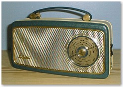
is a classic transistor radio. It is a six transistor circuit having MW and
LW bands. It was made in 1961, at a time when manufacturers were still applying
some imagination and styling to transistor sets rather than shoving them in
uniform rectangular plastic boxes! The PT378 case is vinyl covered plywood,
and is quite solidly constructed. There were in fact several related models,
including the PT208 which, as its name suggests, had MW and bandspread Luxembourg
bands. Similar models were branded Ferranti, Invicta and Pye.
This
is a classic transistor radio. It is a six transistor circuit having MW and
LW bands. It was made in 1961, at a time when manufacturers were still applying
some imagination and styling to transistor sets rather than shoving them in
uniform rectangular plastic boxes! The PT378 case is vinyl covered plywood,
and is quite solidly constructed. There were in fact several related models,
including the PT208 which, as its name suggests, had MW and bandspread Luxembourg
bands. Similar models were branded Ferranti, Invicta and Pye.
I purchased two for �5 at the Spring 2000 Shifnal
Radiophile swapmeet, from Steve Harris (On the Air). They were sold as-is, one
was missing the tuning knob, and both were fairly tatty. The aim was to get
one good set out of the two.
From a quick internal inspection it appeared
that the one with the missing knob and worse case actually had the better innards.
The set with outwardly good appearance had a cracked PCB and a broken waveband
switch.
Repairs
Dismantling these sets is quite tricky. The back
can be removed easily enough, because this has to be removed to replace the
battery (a PP7 - no longer available). Remove the two screws holding the waveband
switch and volume control trim, this also removes the switch actuator. Remove
the screw holding the battery lead retaining P-clip. Then remove the tuning
control. The outer knob is retained with a special screw which can be released
with a pair of fine pointed nose pliers. The inner knob then pulls off � once
the flats on the shafts are aligned. One inner knob broke during this operation,
but the other one came off easily.
According to the Trader sheet (number 1546) there
are two variants of this set, one using Mullard transistors and the other using
Newmarket devices. There are various component value and minor circuit changes
between the two. The PCBs are slightly different too.
One of the sets (the one with the cracked PCB)
was a mix of the two! The RF and IF transistors were Newmarket types and the
detector diode, driver and output transistors were Mullard. The PCB was for
the Newmarket version and the component values (even those in the output stage)
were the Newmarket ones.
The other set (the one with the good PCB) was
different again! This used different Newmarket transistors, and had a few circuit
differences. The circuit is actually fairly similar to the PT208 (apart from
the lack of bandspread) so I suspect that it might be yet another different
model which I have not yet discovered! The PT208 is stated as having a reflex
IF stage, which means that the same transistor amplifies both IF and audio.
I removed both PCBs completely, so they could
be tested on the bench without the cabinet getting in the way. I used a regulated
9V power supply in place of the battery, and a test loudspeaker.
I started by checking the cracked PCB. Surprisingly
it worked, but the broken waveband switch needed some fiddling to get it to
connect. On local stations the reception and sound quality was good, but on
anything more distant the set struggled to receive anything worthwhile. Some
trimming of the IF cans bought about some improvement, and the set then worked
about as well as can be expected from a 6-transistor set (which is the transistor
equivalent of a valve short-superhet). If I was to use this PCB I would need
to do something about the waveband switch, which could be difficult.
So I tried the other set. Nothing. It popped
when switched on, and the emitter resistor for the output transistors was dropping
a few tens of millivolts so I assumed the output stage was OK. But a screwdriver
on the wiper of the volume control did not produce any buzzing. A few voltage
checks proved that the driver stage was not working, and a few resistance checks
suggested that the resistors in the area were probably OK. I removed the transistor
for testing. I have a transistor tester that makes quick work of this job, but
in this case a meter would have been sufficient to show a near-short between
base and collector.
I didn't have a Newmarket NKT274, so I fitted
a Mullard OC81D, which is the device fitted in this position in the Mullard
transistor version of the set. The resistors in this area of the set are the
same in both versions. The set then worked, but the performance was worse than
the other one! The broken ferrite rod would account for some of this, but the
set was also prone to whistles and instability. Normally I would not bother
to pursue this any further if I already have a better working chassis. But in
this case I was interested to see what effect the reflex IF stage and the improved
output stage would actually have.
I glued the broken sections of the ferrite rod
with Super Glue. Another look at the waveband showed that I was actually receiving
MW stations with it set to LW!! When switched to MW it received nothing. As
I was staring at the PCB and wondering where to start, I noticed that the MW
winding on the ferrite rod was broken on two adjacent turns near the middle.
I carefully removed the broken turns and unwound half a turn from each good
end. I then twisted these together, soldered then (the insulation melts away
when heated with a soldering iron) and applied a drop of superglue to secure
the joint.
The set then worked well on MW. In fact it worked
rather too well! Even with the volume at minimum a local station would break
through. This is partly a result of the single transistor stage acting as IF
amplifier (before the volume control) and AF amplifier (after the volume control).
With a strong signal and the loading of the detector diode on the stage some
breakthrough is probably inevitable. The set was also slightly prone to instability
and whistles. The PT208 service data shows an 8K2 resistor in parallel with
the primary of the second IF transformer, but none was fitted in my set, although
the holes existed in the PCB. The data for the PT378 states that a resistor
(typically 4K7) may be fitted in this position in some sets, if instability
is a problem. I tried an 8K2 resistor which bought about some improvement. I
then tried 4K7, which was much better. The instability was gone, the gain (although
still high) seemed more controlled, and the sound quality was improved. I found
an appropriate vintage 4K7 resistor and fitted it properly to the PCB.
The only problem remaining was the lack of LW.
I checked the continuity of the aerial coil and the waveband switch, but all
was OK. Since the set was receiving MW stations faintly on LW, I thought the
problem was likely to be due to the local oscillator continuing to run at MW
frequencies when on LW. My test meter has a frequency range, so I connected
this to the collector of the mixer-oscillator transistor. I noted the reading
on MW (about 1.4MHz) then switched to LW. It scarcely changed, confirming my
suspicion. When the set is switched to LW and additional fixed capacitor (200pF)
and small variable capacitor are connected in parallel with the tuning and other
capacitors to drop the frequency. But in my set the connection between these
components and the ground tag on the tuning capacitor was broken. With this
resoldered the set worked fine on all wavebands.
The circuit uses six transistors in a configuration
that is intended to give the performance of a seven transistor circuit. It nearly
succeeds, but not quite. Presumably transistors were expensive in the early
60s, otherwise there is no reason to use a seventh transistor to do the job
properly. I have not seen this configuration in other sets, so I assume it was
not that successful, or was difficult to get working properly.
In any event I decided to use this PCB, rather
than the standard one. The performance was better, and the waveband switch worked
properly. The other one will be kept (together with the other bits of the second
set) and either used in another set or stripped for spares.
Cabinet Repairs
With a working PCB, I now needed to sort out
the best cabinet. I connected the PCB to the speaker in that cabinet, and found
it was faulty. The speaker from the other set was OK, so I decided to use that
one. The reason for the problem with the first speaker was that the voice coil
was jammed. The cause was obvious enough � the centre screw was loose and the
magnet had moved. It�s quite tricky trying to re-centre it though � and since
I didn't need it right away, I just labelled it and put it away to fix if I
need it for another job.
 I
then dismantled the better cabinet as far as possible. The handle and all the
brass trim could be removed easily from inside the cabinet. The first job was
to remove the dirt and grime from the cabinet and removed trim, which was easily
achieved using foam cleanser. The cabinet had suffered some minor damage in
the back corner where the battery lives. The plys of the plywood had come apart,
and a small amount was missing. Although this was not visible from outside,
I repaired it with wood glue and wood filler.
I
then dismantled the better cabinet as far as possible. The handle and all the
brass trim could be removed easily from inside the cabinet. The first job was
to remove the dirt and grime from the cabinet and removed trim, which was easily
achieved using foam cleanser. The cabinet had suffered some minor damage in
the back corner where the battery lives. The plys of the plywood had come apart,
and a small amount was missing. Although this was not visible from outside,
I repaired it with wood glue and wood filler.
The brass trim was rather dull and tarnished,
and I was undecided whether to polish it or leave it as it was. The domestic
half of the household said that it must be polished if it was to go on display
elsewhere in the house - so that was the decision made!
Often the brass trim on vintage sets is protected
with a thin lacquer, but there did not appear to be any such protection on this
set. Maybe the manufacturers could not justify the expense in the 60s. I polished
the brass with some Brasso and fine wire wool. It came up very nicely, and with
not a great deal of effort! The cabinet itself was polished with a normal household
spay polish, before the handle and trim were refitted. The speaker and PCB were
then refitted, and the set reassembled.
Because the required PP7 batteries are no longer
available, I fitted a holder that takes 6 AA cells. This holder fits comfortably
in the position originally intended for the PP7 if some extra foam rubber is
added, and allows the set to be used with readily available batteries.
The top photo shows the set as I obtained it,
and the bottom one shows it after restoration.
Update
I have since discovered that the version with
the reflex stage is model PT378/1. This would suggest that the change was regarded
as a later refinement rather than a new model. I now have the manufacturers
service data for this model, and it generally matches the set.
Home
This website, including all text
and images not otherwise credited, is copyright © 1997 - 2006 Paul Stenning.
No part of this website may be reproduced in any form without prior written
permission from Paul Stenning.
All details are believed to be accurate, but no liability can be accepted for
any errors.
The types of equipment discussed on this
website may contain high voltages and/or operate at high temperatures.
Appropriate precautions must always be taken to minimise the risk of accidents.
Last updated 14th April 2006.